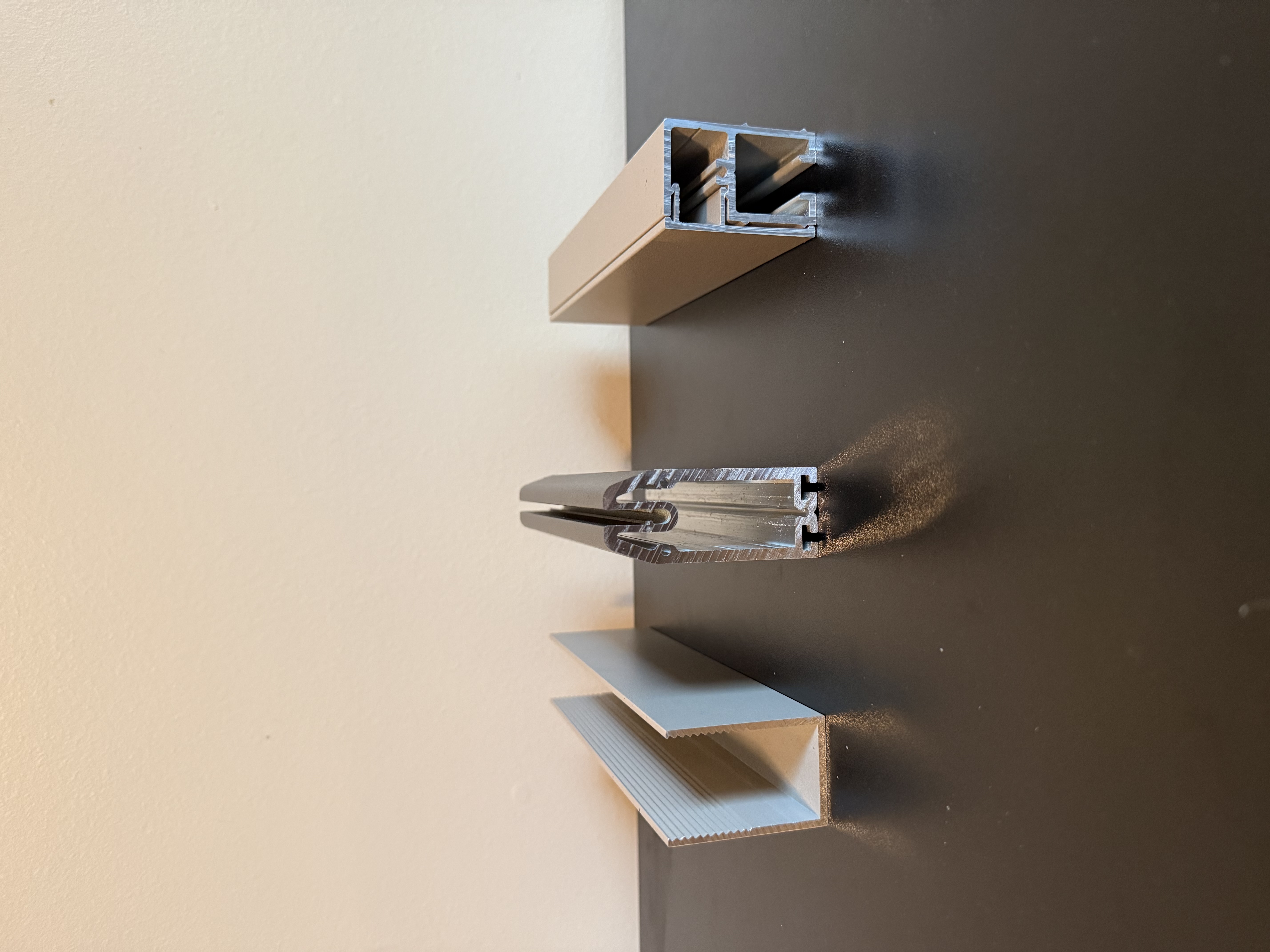
Screen System Extrusion Profiles
Three custom aluminum extrusion profiles designed as a coordinated system — each one handles a different function within the screen assembly but was engineered to work together from the start. Profiles like these are defined entirely by the die geometry, so getting the cross-section right in CAD before anything goes to tooling is what keeps the project on budget. These went from drawings to production-run extrusions.
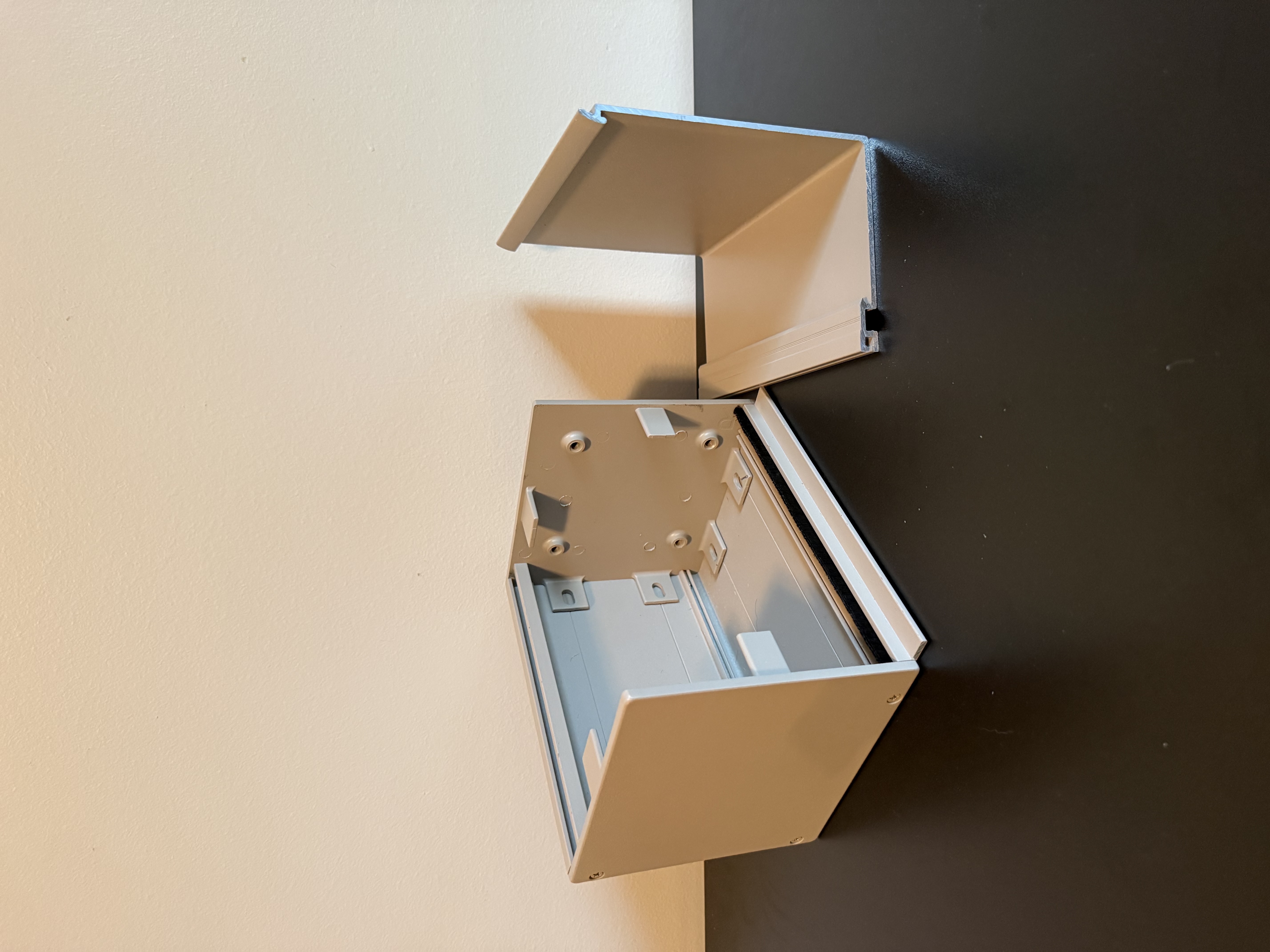
Motor Housing Assembly
The housing body shown here with the hood removed to expose the interior mounting geometry. The housing itself is an aluminum extrusion with all functional features built into the profile, keeping secondary machining to a minimum. The end caps you can see still attached to the housing are cast metal parts — designed to interface cleanly with the extrusion and handle the structural loads at each end of the assembly.
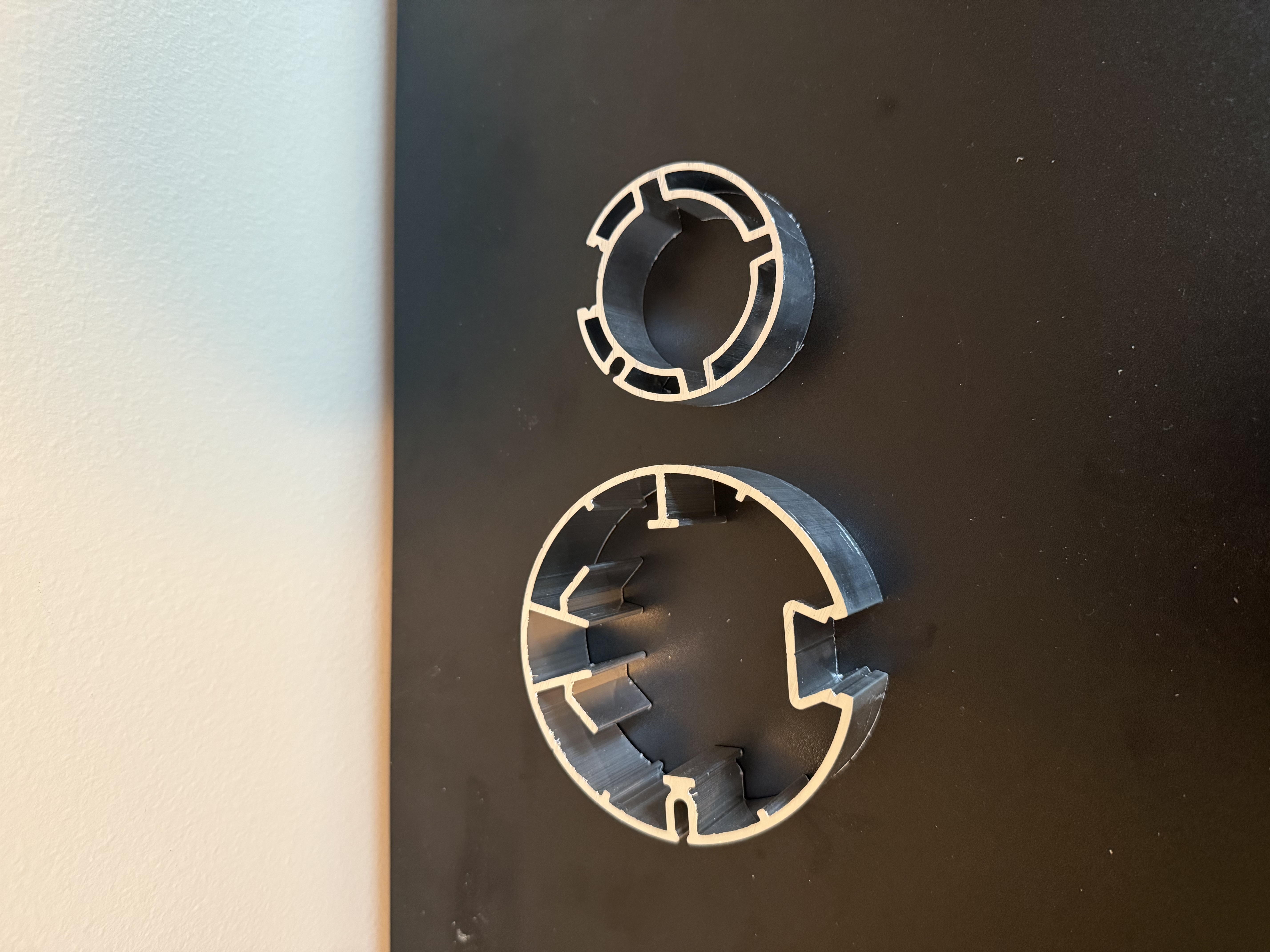
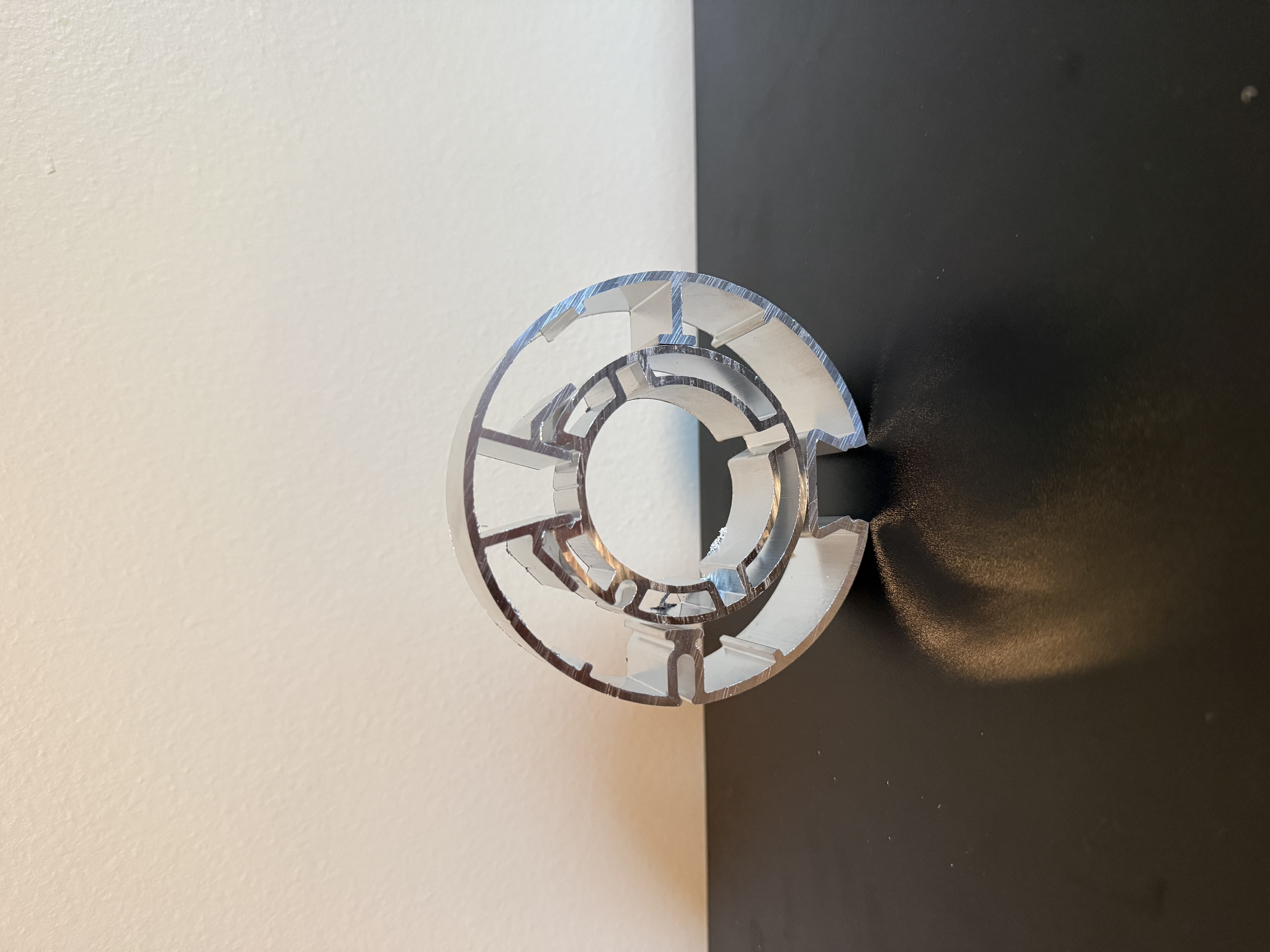
Screen Roller Assembly
A two-part roller assembly where an inner ring nests inside an outer ring to create the full tube the screen winds onto. Both components are custom aluminum extrusions with complex internal cross-sections — the geometry you can see in the profiles is what makes the assembly lock together and interface with the motor drive. The machined ring handles the precision end geometry where tolerances matter most.
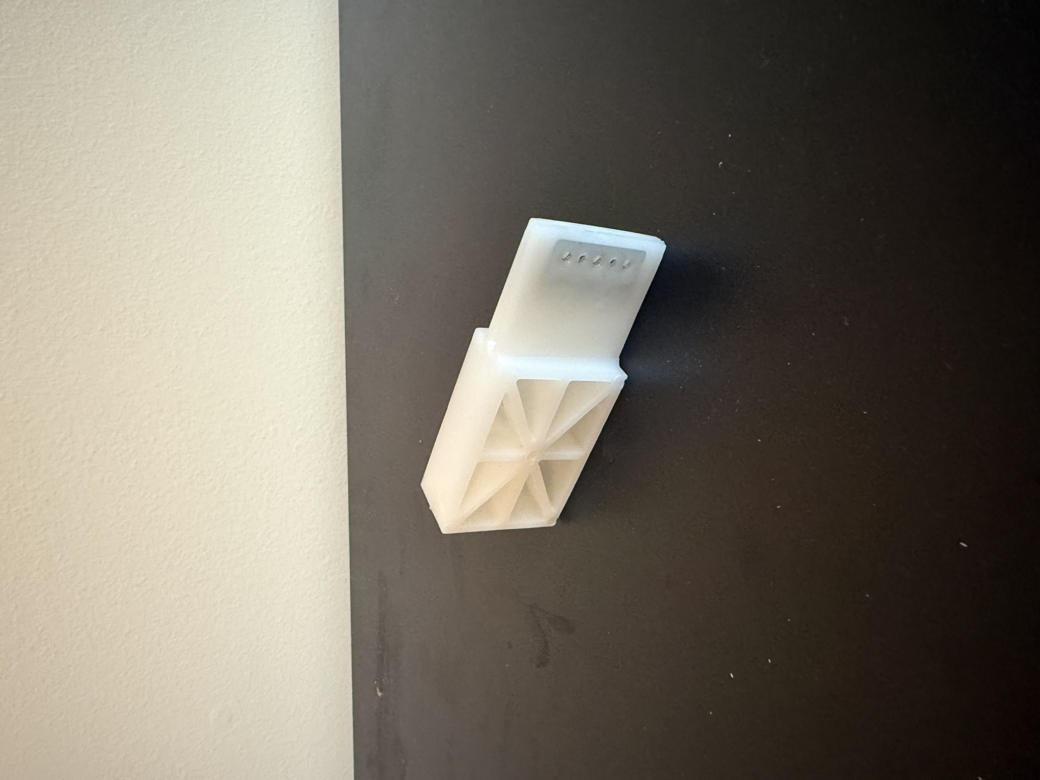
Bottom Bar Probe
Shown here is the production injection molded part — a structural component that attaches the screen to the bottom bar, with an internal spring steel plate for rigidity and countersunk mounting points. The internal ribbing geometry was designed with consistent wall thickness throughout to ensure clean fill and avoid sink. Started as an in-house FDM prototype to validate fit and function before going to tooling.
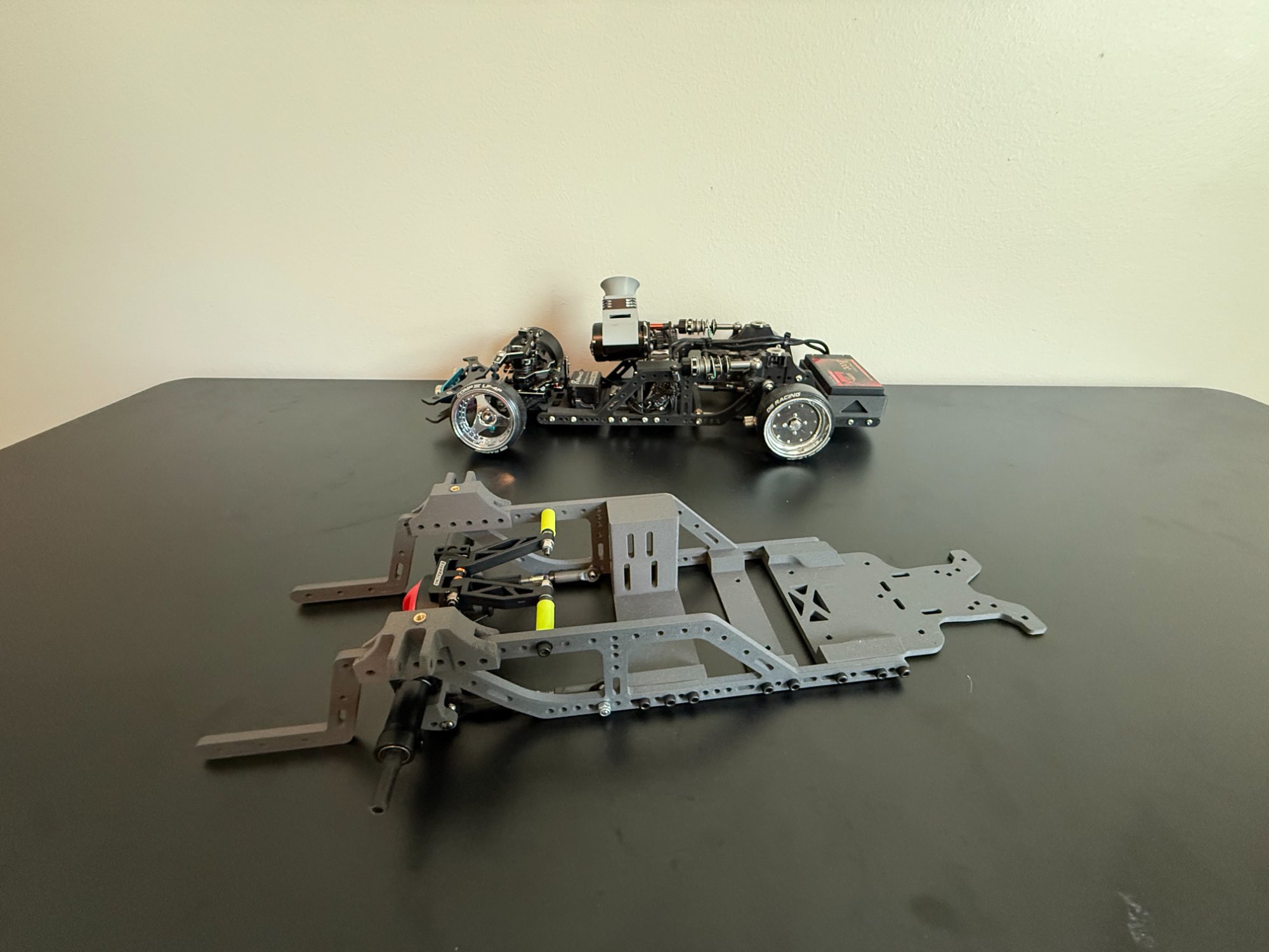
RC Drift Chassis
Full custom chassis designed from scratch for an RC drift platform. Every mounting point, suspension pickup, and electronics bay was laid out in CAD before a single part was printed. Shown fully assembled and operational — produced in PA12-CF carbon fiber nylon for the stiffness-to-weight ratio you'd otherwise only get from machined aluminum.
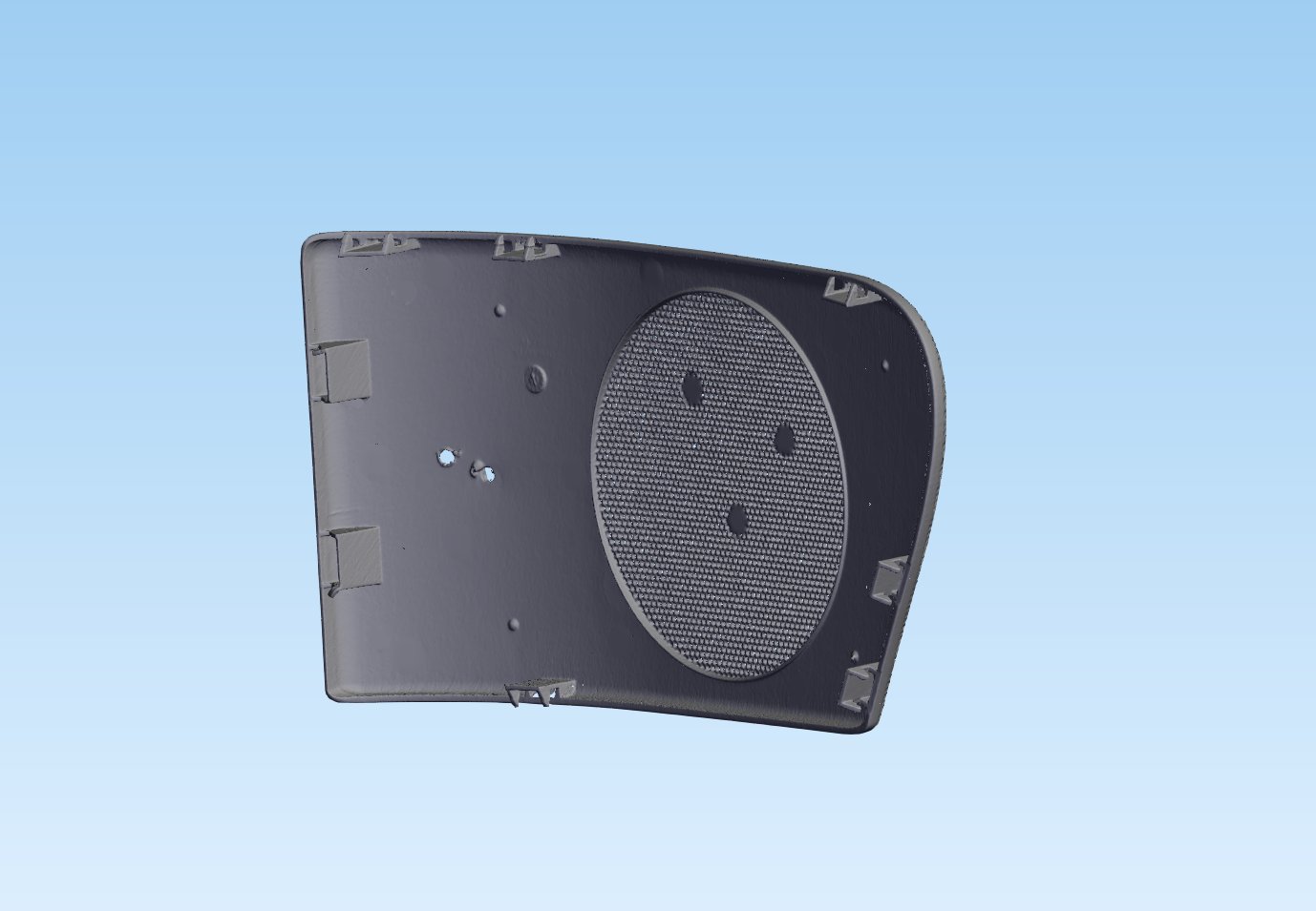
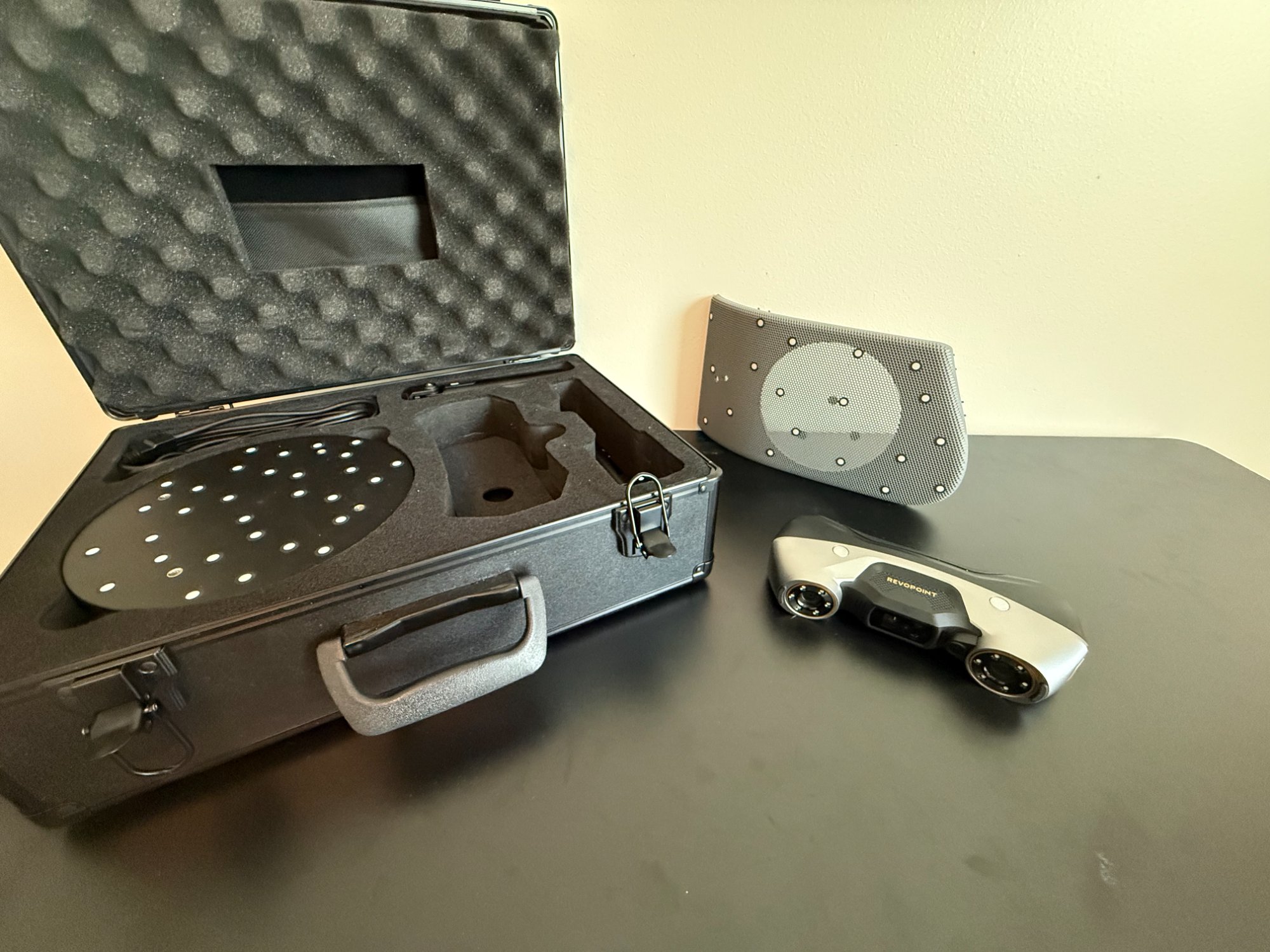
OEM Speaker Grill
An OEM speaker grill that's no longer available — captured via 3D scan using a Revopoint MetroY Pro and rebuilt as a clean, production-ready CAD model. This kind of reverse engineering work is what bridges the gap between a physical part that exists and a drawing that a manufacturer can actually work from.